


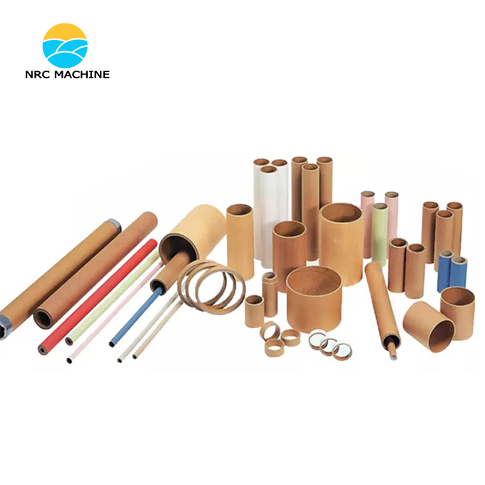
PLC-controlled paper tube cutter consists of the following key parts:
Unwinding Stand/De-reeler: Holds the master roll of paper tube.
Infeed Guide Rollers: Guides the material smoothly into the cutting area.
Feed Mechanism (Servo Motor or Stepper Motor): This is critical for accuracy. It pulls the material forward a precise length for each cut. A servo motor with an encoder is most common for high-speed, high-precision applications.
Cutting Mechanism:
Rotary Cutter: A circular blade that spins continuously. The material is fed into it at a synchronized speed. Ideal for high-volume, continuous cutting.
Guillotine Cutter: A blade that moves up and down. The material is stopped during the cut. Good for thicker-walled or harder tubes.
Saw Cutter: A toothed blade for very thick or composite tubes.
Clamping Unit: Holds the tube firmly in place during the cutting process to prevent deformation and ensure a clean, square cut.
Discharge Conveyor: Moves the finished cut pieces away from the cutting area.
Sensors:
Rotary Encoder: On the feed motor or a separate roller for precise measurement of material length.
Proximity Sensors: To detect the home position of the cutter and clamp.
Photoelectric Sensors: To detect the presence/absence of material (to prevent running empty) and to count finished pieces on the conveyor.
Human-Machine Interface (HMI): A touchscreen panel for the operator to set cut length, quantity, production speed, and to start/stop the machine. It also displays alarms (e.g., "Material Jam," "Blade Worn," "Low Air Pressure").
The PLC (The Brain): The central unit that reads all inputs (sensors, HMI commands), executes the control logic, and controls all outputs (motors, actuators, solenoids).
2. Control System Architecture
The system architecture typically follows this pattern:
HMI (Touchscreen) <--> PLC <--> Field Devices
Inputs to the PLC: Signals from sensors (proximity, photo-electric, encoder pulses), buttons from the HMI (Start, Stop, Jog), and set parameters from the HMI (Cut Length, Quantity).
Outputs from the PLC: Commands to the Servo Drive (for precise positioning), the main drive motor, the cutter motor, the clamping solenoid valve, and the conveyor motor.
3. PLC Control Logic and Sequence of Operation
The PLC program follows a sequential or state-based logic. Here is a typical cycle:
Initialization & Homing:
When the machine is powered on, the PLC runs a homing routine. It moves the cutter and clamp to their known "home" positions using the proximity sensors.
Standby & Parameter Setting:
The operator enters the desired Cut Length and Quantity on the HMI.
The operator presses the "Start" button on the HMI.
Cycle Start:
The PLC activates the feed mechanism (Servo Motor).
The PLC monitors the rotary encoder pulses to measure the exact length of material fed.
Positioning and Stopping:
Once the PLC calculates that the desired cut length has been fed, it sends a stop signal to the servo motor.
Clamping:
Immediately after the feed stops, the PLC energizes a solenoid valve to activate the clamping unit, securing the tube.
Cutting:
Once the clamp is confirmed to be closed (via a sensor), the PLC starts the cutter motor and initiates the cutting motion (e.g., by rotating the rotary cutter or lowering the guillotine).
A sensor confirms the cut is complete.
Unclamping & Ejection:
The PLC de-energizes the clamp solenoid, releasing the tube.
The PLC starts the discharge conveyor to move the finished piece away.
Loop and Count:
The PLC increments the "Pieces Cut" counter.
It checks if the target quantity has been reached.
If not, the cycle repeats from Step 3.
If the target quantity is met, the machine stops and notifies the operator.
Technical Parameters | control system | ||
Cut Paper Tube inner diameter | 50-1 30 mm | power supply | 380V three-phase 50Hz |
Cutting tube wall thickness | 3-15 mm | ||
Main pipe length | 150 0mm | Controller PLC | Xinjie |
Cutting length | 60-1500mm | Main motor | 2.2kw |
Cutting speed | 30 times/minute | Cutting method | Multi -tool |
Loading | automatic | Operation panel | Xinjie touch screen |
Cutting | automatic | bearings | Harbin |
Fixed pipe method | Automatic chuck | Pneumatic components | Hengyi Pneumatic |
Adjusting knife length method | CNC servo | Signal components | Shanghai Engineering |
Operator | 1 person | electrical components | Chint |
Working air pressure | 0.6Mpa | Included accessories | |
Machine size | Toolbox | 1 set | |
Host size | 5000 *900* 1500mm | blade | 5 |
weight | 2 0 00 KG | ||


